have not build one yet. just sharing.
1 Like
I adapted the design using standard plain 2.5mm2 copperwire, and built my own 868 MHz version of this antenna. Works really well!!
info for the mods here:
http://lab.speleo.nu/antvking.php
1 Like
I purchased the same antennae and two others, hooked them up to the N1201SA box. These are the results vs the stock TBeam units:

So, definitely better than the stock antennae. The Noyito are not super awesome at 915MHz, but the Superbat sure do measure well.
Went out for a quick range test this evening and got exactly the same results vs the stock TBeam units. I think this has more to do with 915’s inability to penetrate obstacles than antenna effectiveness. Need to do some A/B/C rssi tests in an open area.
BTW, can anyone tell me which ohm rating I should be looking at on the PS100 N1201SA? I was expecting to see ~50ohms, but they’re each kinda all over the place. This page indicates that the writer is looking at Z.
5 Likes
Hey Jefish
That’s a really good article link !
As you see, you will target impedance Z as close to 50 ohms as this is the target of most board output stages and coax cables (take care, some sat and classic TV cables are 75 ohms). Higher Z means less power will come out of your transmitting stage; lower Z will risk to burn the output transistors.
Testing antennas inside can give very different results due to wall reflections. It’s better to test outside and not too close to the ground.
Ok, Z is the value I’m interested in. Good to know, thank you! When a beginner sees three ohm fields on the tester screen, it’s a bit confusing. 
Any tips on how high is too high, antenna is garbage? Or is “as long as an antenna is Z>50, just use SWR to determine usefulness” the rule?

Beacon setup… RPI zero running a python script sending my call sign plus a message count and time stamp. A heltek . Antenna made of brazing rods cut for 915mhz.
1 Like

@ets354 Can you share your python code?
Thanks.
Informal signal test of new antennae. 30m apart, no obstacles, devices ~5m from any objects/structures.
TBeam RSSI -75
Noyito RSSI -65
Superbat RSSI -65
Need to try longer distances, but without that data, I think I’d opt for the shorter and much more portable Noyito at this point.
I’d rather see in terms of efficiency, between the amount of power our device consumes, how much of that power the device delivers to the antenna, and the percentage of that power the antenna is radiating towards the receivers.
Especially in low power RF applications it’s very important to have overall optimum efficiency. Uncorrect matching means a lot of power will be lost: SWR of 2 means half of your power is lost (so I usually dispose or retune the antenna). Same for too high or too low Z, which means a great deal of your power will not be transferred to the antenna. Good info here
To get good efficiency means
- to spend money on a good commercial antenna from a trusted supplier (can be expensive),
- to tune any mismatched antennas (I experienced some dead cheap spring coil antennas could be improved by stretching the coil bit by bit, which would improve SWR but raised the center frequency, so I eventually cut a bit of the top - it also changed the overall bandwidth but sometimes gave some real good results)
- to build your own antenna and tuning it the best you can = the cheapest and the fun way!
In both last cases, investing 130 euros in a cheap VNA and 3 callibration loads proves to be worth the money.
Start making things a bit too long and then shorten them until the result is okay (antenna length changes frequency, adjusting radials length for adjusting the Z point).
Keep in mind that this kind of antenna tuning is mostly a process with no turning back. As Andreas ‘SensorsIOT’ describes in his excellent video about antenna tuning : it’s easier to cut than to extend !
2 Likes
Does anyone have a set of Motorola DTR600, DTR700, or similar 900 MHz two-way radios that could try out a rubber duck antenna like the PMAF4024?
I don’t think the RF performance would be any better than the cheap half-wave dipoles, since at 7 inches, that’s almost certainly what they are. However, I do think they’d be more rugged for those of us using hard-sided enclosures for biking, hiking, etc.
It’s worth mentioning that you can pretty much ignore the stated gain specs unless they come from established antenna companies and are backed up by reputable tests. On paper, a perfect halfwave dipole (and by extension, a quarter wave monople with a ground plane) has a gain of 2.7dBi, and real world antennas aren’t perfect. If the stated gain for a given design is higher than the theoretical calculated gain for that design, it’s a lie, plain and simple.
As for SWR, it’s important to remember that you need an SWR under 2:1 to protect the transmitter, but SWR isn’t a measurement of how well an antenna works. A 50 ohm resistor (in radio, we call it a dummy load) will have a perfect SWR of 1:1, but it’s a terrible antenna. The only way to practically tell how “good” (efficient) an antenna is is to measure it’s performance.
https://github.com/JFDI-Consulting/TTGO-ESP32-LoRa-Antenna-Tester
’Min, max and mean are calculated for RSSI, SNR and frequency error. The firmware starts in receive mode. A press on the user button will send 10 test messages, time how long it takes to send and receive the ACK, and calculate RSSI etc on the received ACK messages. You can press the user button again within the 5 second timeout to send another set of 10 test messages and have their stats combined with those of the previous set. The stats can be zeroed by holding the user button down for 1.5 seconds. Alternatively you can just reset the device.'
-
Works nicely for me. He sets the Tx power high though. I think an antenna tester should use the lowest power practical. An easy tweak.
-
Perhaps similar stats might be built into a ‘set up mode’ in later versions?
-
3 Likes
I really need to learn to build my own bins. 
In the meantime, I’ve been using a modified version of LilyGO’s range test app, https://github.com/jasonfish/TTGO-T-Beam
1 Like
For a little guidance on aerial selection: https://github.com/meshtastic/Meshtastic-device/wiki/Aerial---antenna-information---selection
Yes… It’s actually another post. I just added a message count. And weather
My take of someone else post. Sorry, I forgot who.
import meshtastic
import time
count = 0
interface = meshtastic.StreamInterface()
while 1:
str = time.strftime("%a, %H:%M:%S", time.localtime())
str =str + " \n\rDennis CQ CQ CQ " + ("\n\r message count = %d " %count) + “\n\r”
interface.sendText(str)
print(str)
time.sleep(60)
count += 1
3 Likes
The script @ets354 added reminds me of one possible enhancement of the wiki files: @geeksville, how about creating a wiki page for python scripts? This could eventually grow to a valuable resource for Meshtastic users.
There could be four subtitles for each of the entries: title of the script, short description (intended usage), script with comments, and additional information (a place for output demonstrations and pictures).
2 Likes
Great idea. Anyone can edit and create new pages in the wiki. It could also link the 3rd party projects that are using the API.
1 Like
does this come in 923? thank you
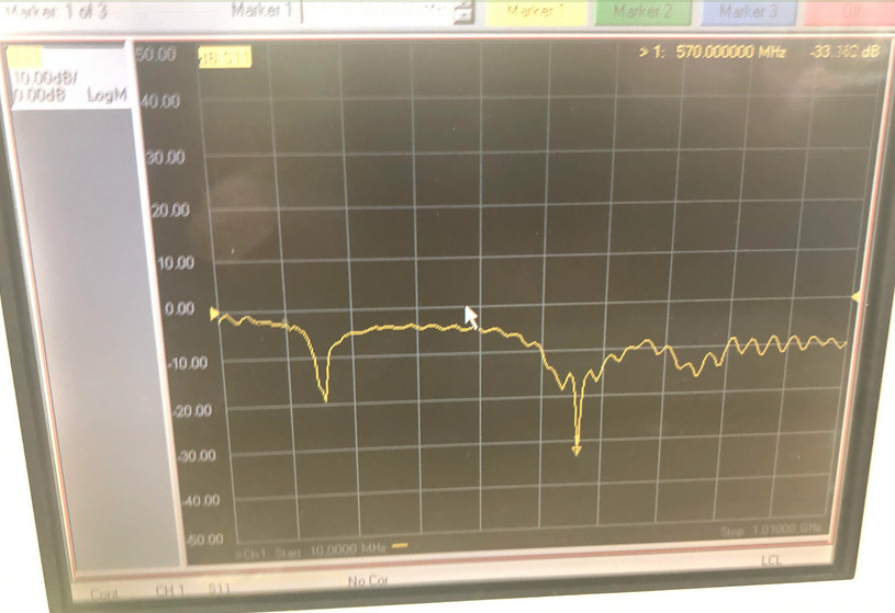
I received mine today and just checked the comments on ali express - they don’t look very promising actually for the advertised frequency of 433 MHz ![]()
Resonates at 162Mhz and 570Mhz, inappropriate! - 26 Jul 2020

The antenna is not suitable for 433 MHz. This is an antenna under 172 MHz, at this frequency it has good characteristics. On 433 MHz I do not advise. - 18 Jun 2020

poor match at 433MHz Resonance at 570MHz and 170MHz - 20 May 2020
2 Likes